 英语
英语 中文简体
中文简体 德语
德语 俄语
俄语 西班牙语
西班牙语 法语
法语
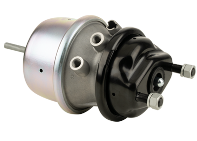
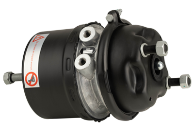
A flanged cover is secured to the rim portions of the cup-shaped housing and piston to prevent inadvertent opening of the emergency brake chamber 22 and release of the power spring. An annular skirt-like rim portion of the cover engages the flanged rim portion of the piston to retain the power spring in compressed condition. The inverted second end portion of the tubular diaphragm is received around the rim portion of the piston to secure it therearound in sealed relation with the piston. The piston cup-shaped portion is biased against the generally radial intermediate portion of the cover permitting use of a power spring having improved performance over conventional designs.
The diaphragm and the piston are connected by an actuator rod 60 which extends through a central opening 64 formed in the end wall of the housing section 51 of the service brake portion 12. The other end of the actuator rod is aligned with the push rod 18 and is supported by a reaction plate 62 received in a central aperture 63 in the end wall of the housing section 21 of the parking brake portion 12 abutting against a spring seat 48 disposed between the diaphragm and the piston to urge the plate 36 and the push rod to a retracted position relative to the housing section 51 of the service brake portion.
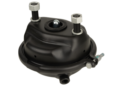
When a vehicle is being driven, a pneumatic pressure is applied to the pressure plate by a compression spring 68 which is provided in the lower service brake chamber 26 and extends from the piston through a port 54 in the flanged cover. When the brake actuating lever is operated to apply the service brake, the compression spring 68 is compressed by the force of the retracted reaction plate 62 to urge the push rod into engagement with the flanged plate 36 and the diaphragm.
To apply the parking brake, the elastomeric diaphragm is depressed by the force of the return spring 72, which is compressed by a compression spring 74 in the service brake chamber 26, against the force exerted by the actuator rod 60. The action of the return spring 74 against the piston and the plate will continue to apply a force against the flanged plate 36 until it is released by a sufficient amount of braking pressure to overcome the retraction force of the actuator rod.
