 英语
英语 中文简体
中文简体 德语
德语 俄语
俄语 西班牙语
西班牙语 法语
法语
The characteristic of the dynamic braking system is that the driver's body is only used as a control energy source, not a braking energy source.
In the dynamic braking system, the energy used for braking is the air pressure generated by the air compressor or the hydraulic energy generated by the oil pump, and the air compressor or the oil pump is driven by the car engine.
There are three types of dynamic braking systems: pneumatic braking system, pneumatic hydraulic braking system and full hydraulic dynamic braking system.
The energy supply device and transmission device of the pneumatic brake system are all pneumatic. The control device is mainly composed of pneumatic control components such as a brake pedal mechanism and a brake valve. Some cars also have a hydraulic control transmission device in series between the pedal mechanism and the brake valve.
The energy supply device and control device of the gas-top liquid brake system are the same as the pneumatic brake system, but the transmission device includes two parts: pneumatic and hydraulic.
Except for the brake pedal mechanism in the full hydraulic power brake system, its energy supply, control and transmission devices are all hydraulic.
One, pneumatic brake system
Pneumatic braking system is suitable for medium-sized and above, especially heavy-duty trucks and passenger cars.
1. Air brake circuit
There are three types of connecting pipelines between the components of the pneumatic brake system: ① Energy supply pipelines, between the components of the energy supply device (such as air compressors, air reservoirs), and between the energy supply device and the control device (such as brake valve) ) Connecting pipeline; ② actuating pipeline, connecting pipeline between control device and brake actuating device (such as brake air chamber); ③ control pipeline, between one control device and another control device The connecting pipeline. If there is only one air pressure control device in the brake system, that is, only one brake valve, there is no control pipeline.
2. Energy supply device
The energy supply devices of the air brake system include: ① an air compressor that generates air pressure energy and an air storage cylinder that stores air pressure energy; ② a pressure regulating valve and safety valve that limits the air pressure within a safe range; ③ improves the energy transfer medium (air ) Inlet filter, exhaust filter, pipeline filter, oil-water separator, air dryer, antifreeze, etc.; ④ It is used to protect the other circuits when one circuit fails, so that the air pressure can not Loss of multi-circuit pressure protection valve, etc.
1) Air compressor and pressure regulating valve
The air compressor is directly driven by the engine through a belt drive. There are single-cylinder type and double-cylinder type. The air compressor of Dongfeng EQ1090E model is single-cylinder air-cooled.
When the pressure of the air cylinder reaches a certain value, the pressure regulating valve can make the air compressor in an idling state, and when the pressure of the air cylinder drops to a certain value, the pressure regulating valve can control the air compressor to inflate the air cylinder.
The working principle of the unloading device of the air compressor and the pressure regulating valve to control the working state of the air compressor is that when the pressure of the air reservoir reaches a certain value, the air pressure acting under the diaphragm assembly of the pressure regulating valve is greater than the pressure of the spring on it. The plate assembly moves upward and drives the core tube to move up together. The valve under the core tube is closed. The air pressure of the air storage cylinder acts on the top of the unloading plunger to move it downward, and the air inlet valve is opened. During the reciprocating movement of the air compressor, The intake valve is always open, and the air compressor is in an idling state. When the air pressure of the air reservoir drops to a certain value, the diaphragm assembly moves down under the action of the spring, the core tube opens the valve, the air pressure above the unloading plunger decreases, the plunger moves up, the intake valve opens normally, and the air compressor Inflate the air reservoir.
2) Filter air pressure regulator
When the pressure of the air storage cylinder exceeds the specified value, the air outlet of the air compressor is directly connected to the atmosphere through the pressure regulating valve, and the compressed air is released to stop charging the air cylinder. The pressure regulating valve and the oil-water separator are combined into one component, namely, filter air pressure regulation valve.
3) Antifreeze
The compressed air output from the oil-water separator or filter air pressure regulator may still contain a small amount of residual moisture. In order to prevent the residual moisture accumulated in the pipeline and other pneumatic components from freezing in the cold season, it is best to install an antifreeze so that when necessary, antifreeze is added to the air path to reduce the freezing point of the water.
The basic working principle of is that when the temperature is lower than 5°C in winter, the ethanol vapor in the antifreeze will enter the circuit with the compressed air flow. After the condensed water in the circuit is dissolved in the ethanol, the freezing point will decrease.
4) Multi-circuit pressure protection valve
The basic function of the multi-circuit pressure protection valve is: the compressed air from the air compressor can be inflated into the air cylinder of each circuit through the multi-circuit pressure protection valve. When a circuit is damaged and leaks, the pressure protection valve can ensure that the remaining intact circuits continue to inflate.
The figure below is a dual-circuit pressure protection valve, which can ensure that when one gas path leaks, the other gas path can continue to inflate.
The figure below is a four-circuit pressure protection valve, which can ensure that the other three circuits can work normally at a slightly lower pressure when any circuit is damaged and leaks.
3. Control device
1) Brake valve
The brake valve is the main control device in the pneumatic service brake system. It is used to follow the action and ensure a strong pedal feel, that is, under the condition of a certain input pressure, it will output the pressure and the input control signal—— The pedal stroke and pedal force have a certain increasing function relationship. The change of its output pressure should be gradual within a certain range. The output pressure of the brake valve can be directly input to the brake chamber as the transmission device as the actuation line pressure, but it can also be input to another control device (such as a relay valve) as a control signal when necessary.
Jiefang CA1091 type car uses a tandem double-chamber piston brake valve. The work of the upper and lower chambers is controlled by the brake pedal, and it can ensure that when one circuit leaks, the other circuit can still work.
2) Manual control valve
The manual control valve can control the parking brake of the car and the parking brake of the trailer. Because there is no requirement for progressive control of the parking brake, the hand-controlled valve that controls the parking brake is actually just a pneumatic switch.
When the joystick is in the position shown in I, the intake valve is closed, the exhaust valve is opened, and the brake air chamber communicates with the atmosphere through the core tube. When the joystick is in the position shown in II, the intake valve is opened, the exhaust valve is closed, and the brake air chamber is vented with high-pressure air.
3) Quick release valve and relay valve
The function of the quick release valve is to ensure that the brake chamber is quickly vented when the brake is released. The quick release valve is arranged on the pipeline between the brake valve and the brake air chamber, close to the brake air chamber. Because it is close to the brake air chamber, the exhaust circuit of the brake air chamber is short, and the exhaust speed is faster . The state shown in the figure below is that the intake port is closed and the exhaust port is open.
The function of the relay valve is to make the compressed air not flow through the brake valve, but directly fill the brake air chamber through the relay valve to shorten the air supply route and reduce the braking lag time. In the state shown in the figure below, the valve is not only leaning on the valve seat of the valve body, but also on the core tube, and both the intake valve and the exhaust valve are closed
.
4) Shuttle valve (two-way valve)
The feature of the shuttle valve is that both cavities of the dual-chamber brake valve can input control air pressure to the trailer brake valve through the shuttle valve to ensure that the trailer brake valve can still be connected to the brake control when one of the two brake circuits of the car is damaged. signal.
4. Brake chamber
The function of the brake air chamber is to convert the air pressure energy into mechanical energy output, and the output mechanical energy is transmitted to the actuating device such as the brake cam, so that the brake generates a braking torque. There are three types of brake air chambers: diaphragm type, piston type and compound type.
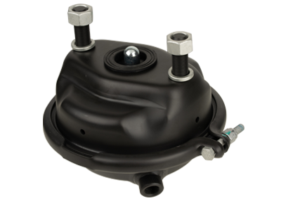
1) Diaphragm brake chamber
The two chambers of the diaphragm brake air chamber are separated by a diaphragm, and the connecting fork is connected with the brake adjusting arm.
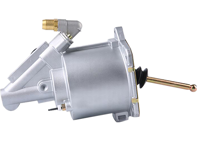
2) Piston type brake air chamber
The piston brake chamber has a larger push rod stroke, and its piston has a longer working life than the diaphragm, but the entire chamber has a more complicated structure and higher cost, and is often used in heavy trucks.
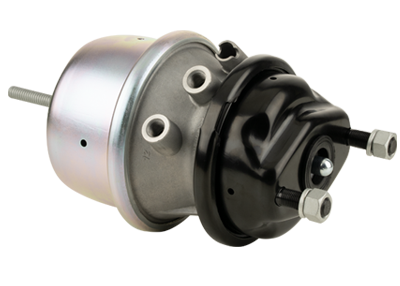
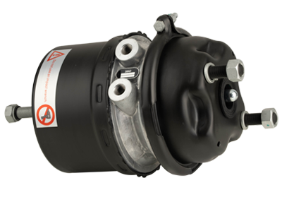
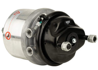
3) Compound brake air chamber
The characteristics of the composite brake chamber are: the brake chamber is composed of two parts, the service brake chamber and the parking brake chamber, and it plays the role of service brake and parking brake.
2. Air cap hydraulic brake system and full hydraulic power brake system
1. Air cap hydraulic brake system
The energy supply device and control device of the gas-top liquid brake system are all pneumatic, and the transmission device is a pneumatic-hydraulic combined type. The air pressure can be converted into hydraulic energy through the power chamber and hydraulic master cylinder connected in series, and the hydraulic energy is transmitted to each wheel cylinder to produce a braking effect.
The advantages of the air-top hydraulic brake system are: ① The pneumatic system is compactly arranged, which reduces the length of the pipeline and the lag time. ② The use of hydraulic wheel cylinders as brake actuation devices reduces unsprung mass. ③ When a trailer is towed by a car that uses a gas-cap liquid brake system, the trailer can be braked by air pressure or hydraulically. ④ The brakes of each axle can be actuated by hydraulic and pneumatic respectively.
2. Full hydraulic power brake system
Full hydraulic dynamic braking system is a dynamic braking device that generates hydraulic action by the hydraulic energy stored in the accumulator or restricting the circulation of the fluid flow.
